


The installation of medium and high voltage systems is governed by a legislative, normative and regulatory framework, which requires the intervention of specialized electrical contractors.
How can the compliance of your installation be approved?
CONTRÔLE RK specializes in Tests and Measurements. We conduct this type of assessment for you during the installation process in order to evaluate their compliance.
The testing usually starts with the measurement of electrical and thermal resistivity of soil, followed by the necessary tests and measurements according to the list below.
OUR LIABILITY
Associating each test or measurement with specific standards governing each application, in order to determine compliance or noncompliance.
OUR SIGNATURE
Since 2006, our involvement in major projects has enabled our staff to acquire advanced skills and solid expertise in tests and measurements on medium and high voltage installations.
TESTS AND MEASUREMENTS
Soil Resistivity
BASIS
A current is injected between two electrodes then into the ground to measure, by means of another pair of electrodes, the potential difference induced by this current.
This is how the soil resistivity is measured before construction in order to get as much information as possible on the capacity of the electric current to flow, and thus determine the location and design of ground electrodes and networks.
APPLICATION
Worksites for:
- Large commercial buildings
- Power distribution stations
METHODS
There are various methods. Although SCHLUMBERGER remains an option, the preferred one is WENNER four-electrode method.
Wenner configuration

STANDARDS
- Std.81 IEEE-1983
- IEEE 81.2-1991
- Other
Soil Thermal Resistivity
BASIS
Thermal resistivity varies depending on the type of materials the soil is made of, and its degree of humidity. Measurement methods are used in situ and in laboratory to determine the thermal conductivity.
These key data are then considered in the calculation of power transmission capacity of a cable. They are also used to assess the level of the surrounding soil dissipation and to choose the appropriate backfill material.
APPLICATION
- Installation of collector system
- Troubleshooting a cable
METHODS
In laboratory:
Compacting soil to the required density then measuring at different water contents, using a probe, to finally draw curve of soil thermal resistivity according to moisture percentage.

In situ:
Digging a 1.2 m deep trench in the power cables layout to measure the thermal resistivity with a probe. These measures are usually taken at 3 locations in the trench walls.
STANDARDS
- ASTM D5334
- IEEE Std 442-1981
Ground impedance
BASIS
The grounding of an electrical system is usually done through the installation of a connection between a supply line neutral and a ground electrode.
Groundings are used to protect people, facilities and equipment, as they are effective bypass means for fault currents, lightning strikes, electric shocks, etc.
APPLICATION
Applies to any electrical installation, except special requirements from the Canadian Electrical Code.
METHODS
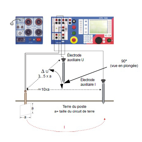
Fall-of-potential method
This method consists in letting a current circulate into the electrode to be measured and noting the influence of this current in terms of voltage between the ground under test and a test potential electrode (U). A test current electrode (I) is used to allow the flow into the electrode to be tested.
As the potential electrode (U) is progressively moved away from the ground under test, a value of impedance is obtained at each step to create a curve that levels out and thereby determines the impedance value of the ground under test.
STANDARDS
- IEEE Std 81-1983
- Other
Step and Touch Voltages
BASIS
These measurements must be assessed in critical areas such as electrical distribution systems like wind farms, factories, etc., as there may be step and touch voltages produced by a phase to ground fault.
It is crucial to measure the step and touch voltages where there is risk of electric shock, in order to ensure the safety of people and animals.
APPLICATION
- Power distribution stations
(Any conductor connected to the ground from a distribution station such as rails, fence, etc.)
METHOD
Test Probe
This method consists in injecting a current in the MALT grid of the installation in order to measure voltage at different points and various locations.
According to standards, measurements are then compared with theoretical values of a secure site calculated in case of fault. If necessary, corrections are made by modifying either the grounding or the surrounding soil.

STANDARDS
- IEEE Std 81.2
- IEEE Std 80-2000
Dielectric Strength (Hipot and VLF)
BASIS
Dielectric tests are essential prior to putting into service a new cable or equipment, or after handling them. The detection of any insulation failure helps avoid more serious damage and power outage delays.
APPLICATION
Installation and maintenance of electrical equipment.
METHOD
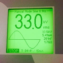
According to established standards for dielectric tests on cables or power equipment, AC or DC voltage is applied for a predetermined period of time. Insulation resistance is then checked to establish if the cable or equipment can be operated.
STANDARDS
- IEEE-400-2001
- IEEE-400-2002
Partial Discharge
BASIS
Partial discharge (PD) is an electric discharge that bridges a small portion of the insulation between conductive parts. PD cannot be detected through standard tests (Hipot, VLF) as these are used only to qualify cables and connections prior to commissioning.
This type of diagnosis (PD) not only reveals the performance reliability of cables, joints and terminations, it also detects any degradation of their insulation.
APPLICATION
Underground collector systems.
METHOD
A VLF voltage is applied for a period of time, according to established standards for dielectric testing of medium voltage cables.
A capacitor, a filter and a data acquisition system are coupled to the VLF in order to check the voltage level of partial discharges and at what stage they appear.
According to voltage levels, standards determine the actions to take, including immediate repair if possible.

STANDARDS
- IEEE-404
- Other
Cable Fault Location
BASIS
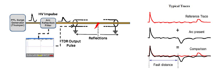
The main goal of any cable fault location is to pinpoint the fault and perform only one excavation in order to reduce the length of intervention and outage.
The latest accurate fault location technologies use shockwave methods: generators causing a loud bang around the fault area, allowing to pinpoint its location by means of an acoustic apparatus.
The work team must however be experienced, knowledgeable and able to use the proper equipment with precision, in order to address the most demanding challenges that may occur with underground cables and joints.
APPLICATION
Underground collector systems.
STRATEGY
- Pre-locating / isolating the faulty section or sector
- Restarting facilities that are not affected by failure
- Pinpointing fault location within targeted section
METHODS
- Arc reflection
- Arc reflection in differential mode
- Electromagnetic impulse
- TDR (radar)
Underground Cable Location
BASIS
It is possible to avoid damaging underground cables during risky excavations.
With underground pipe detection apparatus, electrical cables buried in the ground or hidden beneath a layer of concrete can be located.
APPLICATION
- During construction: to confirm layouts provided by surveyors.
- During repair or installation work: to avoid damaging existing cables.
METHODS
- Locking onto the 60Hz signal emitted by energized cable.
- Injection of a high frequency signal on the cable, then tracing the latter.
- Injection of a high frequency signal near or around the cable with a generator or current donut, in order to locate it without having to power off the equipment.

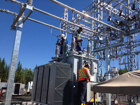
Power Transformer and Switchgear
BASIS
Transformers and switchgear are power equipment with two functions:
- Increasing energy voltage to a higher level for remote transport purposes.
- Decreasing energy voltage level for distribution purposes.
For any worksite requiring an electricity distribution station, it is important to make sure that power transformers and switchgear have not suffered any damage during transportation. Proper operation of each element (POV) should also be checked.
PRE-OPERATIONAL VERIFICATION (POV)
Transformer (verification, inspection, sampling and analysis)
Electrical tests
- Contact Resistance
- Insulation Resistance
- Ratio tests
- Winding Resistance
- Doble Tests - power factor on bushings, windings and surge arresters
- Oil Sampling and Analysis
- SFRA
Switchgear (verification and inspection)
Electrical tests
- Contact Resistance
- Contacts synchronization (disconnectors, breakers, etc.)
- Insulation Resistance
- Doble Tests - power factor on bushings, isolators and surge arresters
- Circuit breaker timing Tests
- Verification of Control Panels
- SF6 Gas Quality Check
STANDARDS
- Neta ATS-2009
- Neta MTS-2011
- CSA Z463-13
- Other
